
This procedure should only be performed by a trained technician or dealer. If you have not been trained on this procedure, contact your dealer or Kilter support instead of performing it yourself.
Refer to the machine configuration page for the wheel/track widths available for your AX-1.
Before you start
- Power off the robot before beginning any adjustment.
- Position the robot on a flat, level, stable surface.
- Wear appropriate protective equipment (gloves, steel-toe boots).
- Have the correct new spacers and matching M10 bolts/nuts ready before you begin.
Safety warnings
Warning: The AX-1 is heavy and its centre of gravity is not at its geometrical centre, making it prone to tilting. Take all necessary precautions to avoid injury before beginning any adjustment.
Note: When unscrewing the wheel frame, make sure the robot doesn't tilt backwards. It no longer has support from the back wheel once the frame is loose.
Note: Wires run from the robot to the wheel through the frame and spacers. Once the wheel frame is detached, do not pull or apply tension to the wires. Rest the wheel frame close to the robot while swapping spacers.
Which spacers do I need?
Select the wheel C-C width you want in the calculator below:
Tools & torque reference
| Task | Tool | Torque |
| Unscrew spacer nuts/bolts | Two 17 mm wrenches (one ratcheting preferred) | — |
| Loosen logo cover (if fitted) | 10 mm spanner (cover) + 19 mm pipe (bolts) | — |
| Attach new spacer | M10 bolts/nuts, 16/17 mm pipe or wrench | — |
| Reattach main wheel | — | 100 Nm |
| All spacer specific bolts | Torque wrench | 40 Nm |
Steps
1. Set up the jack
Using a table-jack with planks is the recommended method for lifting one side of the robot at a time - this avoids having to remove the bumper.
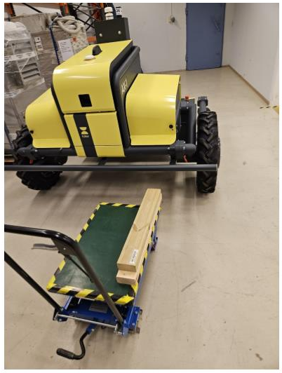
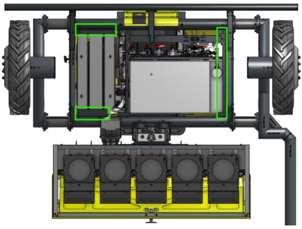
Apply force only to the marked brackets/frame (shown as green rectangles in reference photo below), never to the tank or any other component. The planks used on the jack should be longer than the marked area to keep the lift stable and prevent slipping.
2. Lift one side
Raise the side of the robot you're working on until the wheel is clear of the ground. The robot cannot rest on its wheels while spacers are being changed.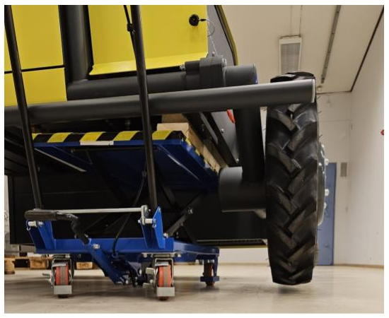
3. Remove the main wheel
Remove the main wheel before working on the spacers — the side frame and wheel assembly are heavy, and removing the wheel first makes the rest of the job safer and easier.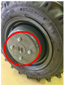
4. Remove the old spacer
Unscrew the spacer nuts and bolts with two 17 mm wrenches (or, if your robot has a logo cover, loosen it with a 10 mm spanner and remove the bolts with a 19 mm pipe).
Keep the wheel frame supported and close to the robot. Do not let it hang from the wiring, and do not pull or tension the cables running through the frame and spacer.
5. Fit the new spacer
Rotate the new spacer so the cable routing slot points inward, toward the robot, and push any excess cable back inside the robot frame. Be careful not to pinch cables inside the tube frame as you tighten.
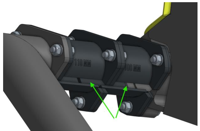
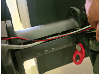
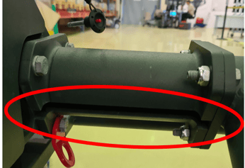
Attach the spacer with the matching M10 bolts and nuts using a 16/17 mm pipe or wrench.
6. Torque the spacer bolts
Tighten the bolts connecting the spacer and frame to 40 Nm using a torque wrench.
7. Reattach the main wheel
Refit the main wheel and tighten the wheel bolts to 100 Nm.
8. Repeat on the other side (if applicable)
Lower the jack and repeat steps 1–7 on the opposite side.
Verify it worked
- The wheel spins freely with no obstruction.
- No cables are pinched or under tension inside the tube frame.
- The spacer's cable routing slot faces inward, toward the robot.
- All bolts are torqued to spec (100 Nm wheel bolts / 40 Nm spacer bolts).