
INDEX
-
Workdata and File Types
-
Kilter Farm - Fields and Workspaces
-
Making a Route
-
Publishing the Route
-
Other Useful Tools
-
Advanced Functions
1. Workdata and File Types
Kilter Farm can build a route from three types of workdata. Better data means fewer unexpected stops. It is also recommended to track the headland, either with other equipment or with the AX-1 itself.
1.a Workdata
| Workdata type | Description |
|
Point workdata Highest accuracy |
GPS-recorded work points from a previous pass with a tractor or other equipment. This method generates the most accurate routes. A single pass per row is preferable, as double passes can create double lines. |
|
Polygon coverage workdata OK accuracy |
Not yet available in Kilter Farm. Once supported, GPS-recorded polygon coverage would be used to generate lines — a less precise method than points, with single passes still preferred. If this is the only data you can export from your equipment, contact Kilter Support for assistance. |
|
AB-line Lowest accuracy |
A single reference line, duplicated across the field at a set width. This should only be used on straight, flat fields with evenly spaced rows — it is the least accurate method, since the robot and the tractor or other equipment can compensate differently for any slope. |
1.b File Types
Kilter Farm accepts workdata in the following formats. Other file types can often be converted into one of these three (ranked in order of preference):
- Shapefiles — the .shp, .dbf, and .prj files (and sometimes more) must all be included together
- .geojson
- KML (uses the .xml format)
Tip: For shapefiles, either export as a ZIP folder or compress the files into one after exporting. The ZIP can be uploaded directly to Kilter Farm.
2. Kilter Farm – Fields and Workspaces
Now it's time to open Kilter Farm and create your fields and workspaces.
If you have not yet set up your account in Kilter Farm, see Getting started with Kilter Farm
2.a Fields
Fields are where you keep all your workdata, workspaces, and routes.
2.a.i Create Field
In Kilter Farm, go to Fields, and Create field.
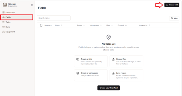
Creating a new field in Kilter Farm.
You can then upload a boundary for the field. Currently, this has no functional role beyond giving a visual outline of the field. After clicking on Create field, you can open your new field.
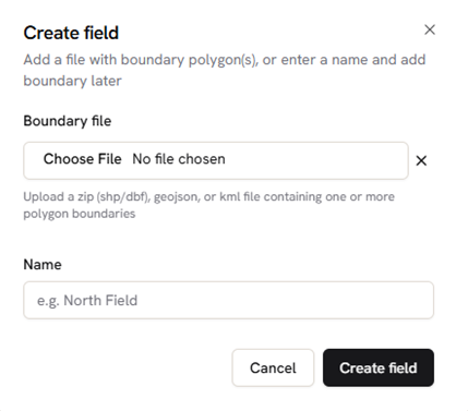
Uploading a field boundary.
If you upload a boundary or files later when you create the workspace and Kilter Farm does not autodetect the CRS, see section 5.f Manually choose CRS.
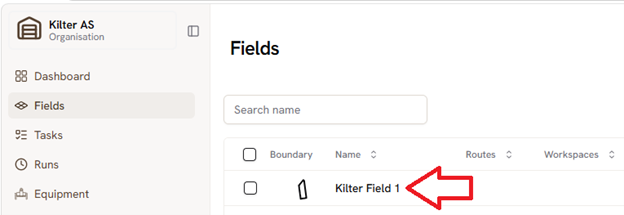
Selecting the newly created field.
In the image below you can see the view inside the field. Here you have three different tabs where you can see the routes, workspaces, and files that belong to this field.
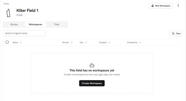 View inside a field in Kilter Farm.
2.b Workspaces
This is the space where you use the data to make routes.
To create a new workspace, click the Create Workspace button, or the New Workspace button in the top-right corner. Using your workdata, you can either upload files, use files you have previously uploaded, or continue without files to start with an empty workspace.
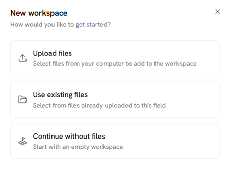
Choosing how to populate the new workspace.
After you make a selection, the new workspace opens automatically with a pop-up that gives an introduction to workspaces and route-making, as well as how to get help from Kilter to make the route.
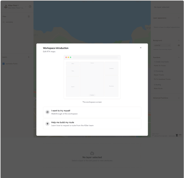
The workspace opens automatically after setup.
2.b.i Workspace overview
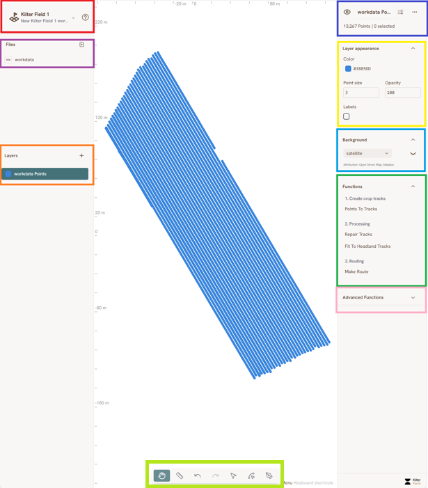
Workspace walkthrough overview.
The workspace is made up of a few key areas, summarized below:
| Area | What it does |
|
Workspace dropdown menu |
Save the workspace, publish the route, and access other workspace-level actions. |
|
Files |
Shows the workdata and files included in the workspace. You can also upload files here using the icon in the top-right corner. |
|
Layer |
Lists the point, line, and polygon layers in the workspace. A layer must be selected before it can be edited. Renaming layers is recommended to keep the workspace organized. |
|
Selection summary |
Shows which layer is selected, what it contains, and how many features are currently selected. |
|
Layer appearance |
Controls how the selected layer looks. |
|
Background |
General background/basemap settings. |
|
Common functions |
The most frequently used route-building tools. |
|
Advanced functions |
Additional functions, sometimes needed when the route or data is more complex. |
|
Toolbar |
Contains tools like measure, select, edit vertices and add feature. |
2.c Route Help
Clicking the question mark by the workspace dropdown menu gives you two ways to get help making your route.
2.c.i Learn
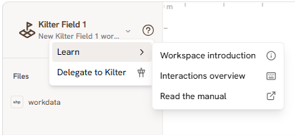
The Learn menu, with resources for making a route.
2.c.ii Delegate to Kilter
If you want help with creating a route, please add all relevant information. This could be info on obstacles, starting point, driving pattern etc. If there is no or little information, it can often be difficult to assist with your issues. Then you can click on Please make route. This will create a support request that will be followed up by us as soon as we can.
If you need urgent help you can also call Kilter Support at +47 960 06 820.
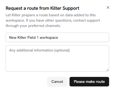
The Delegate to Kilter support request form.
3. Making a Route
In Kilter Farm you can build a route from three types of workdata that you have either uploaded when making the workspace or at a later point. Following the headland section, this guide will take you through all three types and how to make them into tracks. After this, the steps are the same. Fit to headland ensures that the tracks and the headland fit together. Start and end points give you control over where the robot begins and ends up. Then its on to finally making the route with the Make Route function and publishing it.
3.a Headland
The first step is to make the headland. This is where the robot turns and drives to the next row. It will follow the headland line just like other tracks by placing the center points between the two front wheels where the line is. It should be around 3m from the actual rows in the field, so that it has space to turn as it does this on its own axis and the rear wheel will cut across the rows if too close.
If there are any hindrances in the field, headland lines should be made so that the robot will turn before it runs into the hindrance. Sufficient space for the robot to turn will still be important.
The headland can either be tracked or be drawn manually in Kilter Farm. Tracking is preferred, especially for more complex fields, as manually drawn headland usually needs adjustments after testing.
3.a.i Tracking headland
This can be done with various tracking equipment or the robot itself and then uploaded to a workspace. Using the robot it can be drawn in the workspace for the given route.
3.a.ii Creating Headland Manually
To draw a headland manually, click the + button in the layers menu and choose LineString.
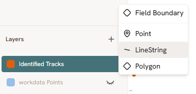
Choosing the LineString geometry type.
A new LineString layer appears. Right-click it and choose Rename (optional), then rename it to keep the workspace organized.
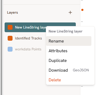
Renaming the new layer to “Headland”.
Use the Add Feature tool  to draw the headland. With the headland layer selected, click once to place each point, and double-click to finish the line. It is often useful to use the workdata such as points and polygons to decide the position of the headland. This will not be possible when using an AB-line. A last resort is then to follow the satellite background image, but this has very low precision.
If you need to adjust the line afterwards, use the Edit Vertices tool  . A vertex appears as a red point on the line that you can drag. If it does not appear, try to refresh the page.
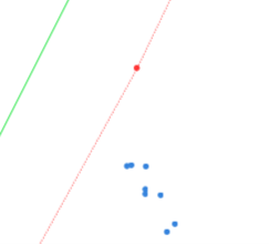
This shows a vertex being dragged, with the old position in green and the new position in red before you let go of it.
Edit Vertices: Click on the line to add new vertices and click-and-drag a vertex to reposition it. To remove a vertex, hold Alt and click on it. If it is hard to select the right vertex, hold Alt while hovering over the line to lock onto the one you want to adjust.
When you are satisfied with your headland you can move on to converting your workdata into crop tracks.
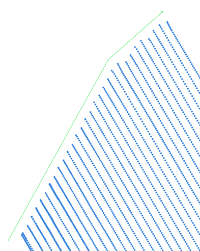
Manually drawn headland (green) together with point workdata.
3.b Point Workdata
The point data you have previously uploaded should look something like this:
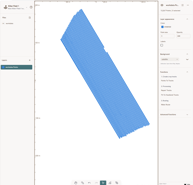
Point workdata layer selected in the workspace.
3.b.i Points to Tracks
Use the Points to Tracks-function to create tracks from the points. Select the layer with the points and hit Enter or click the play button in the bottom-right corner of the box.
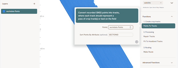
Running the Points to Tracks function.
These newly created tracks may need to be repaired and cleaned.
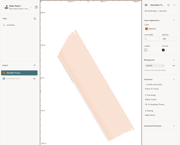
Tracks generated from point data.
3.b.ii Repair and Clean
If the tracks turn out fragmented, use the Repair Tracks-function to join them back together.
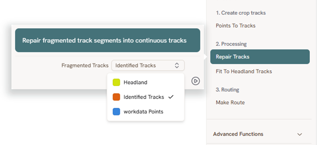
Using the Repair Tracks-function.
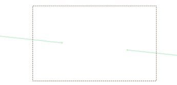
If there are only a few lines to join, you can also do this manually instead of running Repair Tracks on the whole layer. Select the two lines to join — using click-and-drag, or by holding Ctrl and clicking them one by one — with the Select tool  .
.
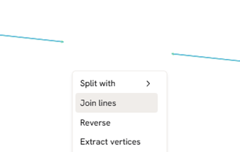
Right-click and choose Join lines.
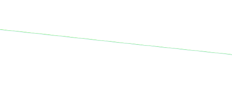
The lines are then joined.
Afterwards, inspect the tracks for unwanted extra lines and delete any you find using the Select tool and the Delete key.
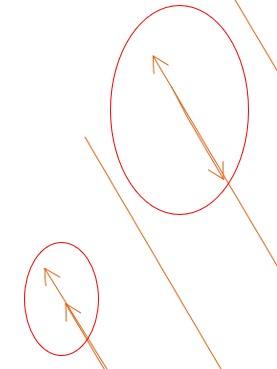
Example of unwanted extra lines to delete.
Continue here: 3.e Fit To Headland
3.c Polygon Coverage
Polygon coverage is the second-best workdata to build a route from. However, generating lines from polygon coverage is not currently supported in Kilter Farm. We recommend contacting your GNSS system provider to get information on the possibility of extracting point data. If this is the only data you can source, make a support request from the workspace or contact Kilter Support at support@kiltersystems.com for assistance.
3.d AB-line
An AB-line is the least precise source of workdata. It only works on flat fields with minimal tilt and straight, parallel rows, and even then some imperfections can occur. The larger the field, the more likely this becomes. The robot has no sensors to keep it within its row and will follow the selected path exactly, so it cannot compensate for imperfections the way a tracked or point-based route can.
An AB-line can be imported either as a line or as points. If it was imported as a line, the first step below can be skipped.
3.d.i Points to line
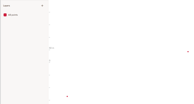
AB-line workdata imported as points.
If the AB-line was imported as points, select the points, right-click and select Points to line to convert them into an AB-line.
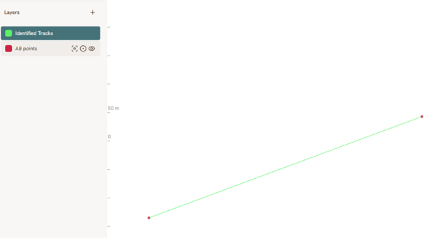 The resulting AB-line.
3.d.ii Generate Tracks
Expand the Advanced Functions dropdown if it is not already open and select Generate Tracks. Fill in your AB-line and headland.
Set Distance Between Rows to match your robot — this should be the distance from wheel center to wheel center.
If the rows are offset from the AB-line by a known amount, enter this under Initial Offset.
Lastly, if you have a specific pattern for your field, you can use Pattern. For example, if you have 10 rows with even 1,8m spacing and then a 3m gap throughout the whole field, you can input “3, 10, 1.8”. Be aware that the pattern will override the distance between rows.
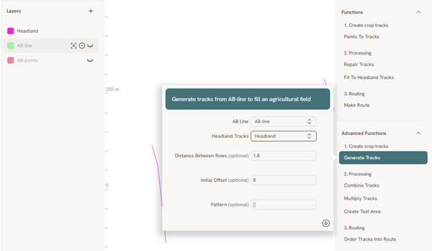
Configuring the Generate Tracks function.
The result often needs a little cleanup. Here, the long lines were generated due to the headland not matching each other. This could be correct and require the lines to be deleted, or the headland to be adjusted.
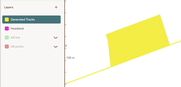
Tracks generated from the AB-line before cleanup.
Use the Select tool + Delete to remove any unwanted lines. Alternatively, adjust the headland to fit these rows as well.
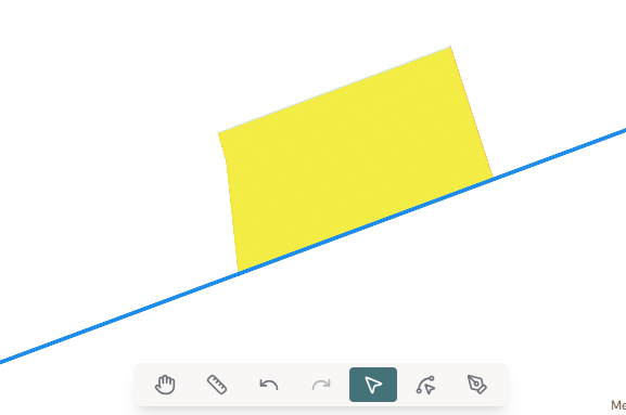
Selecting an unwanted line to remove.
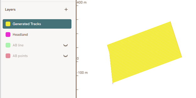
Tracks after cleanup.
3.e Fit to Headland
Once you are happy with the headland, use the Fit to Headland Tracks-function to adapt the tracks to it. When the geometry of a field is more complex, it can help to adjust Max Extend Row Ends down from its default 200 m setting — ideally to just larger than the distance the longest row needs to extend to reach the headland. You can use the Measure tool  to check this. This adjustment keeps the amount of cleanup needed afterwards to a minimum.
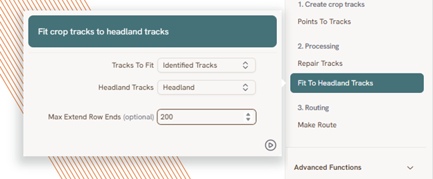
Running the Fit To Headland Tracks function.
This function can also create new lines in some scenarios, again more likely on complex field geometry. It can help to compare the number of LineStrings in the original track layer with the fitted layer — this can be checked in the top-right corner. If there are more lines after than before, it indicates that some extra lines were created by this function. Inspect your tracks and delete unwanted ones.
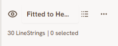
Checking the number of LineStrings in the fitted layer.
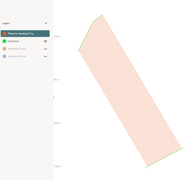
Tracks fitted to the headland.
3.f Start and end points (optional)
Start and end points give you the option to decide where the robot will start and stop. They are optional. To add one, create a new point layer for each and use the Add Feature tool to place the point in the desired position.
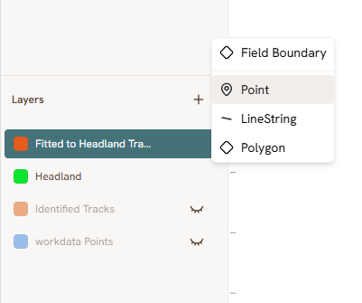
Creating a point layer for the start point.
Use the Add Features tool to click at the beginning of the track where you want to start with. Do the same for the end point in its own point layer, placing it at the end of the track you want to finish with instead.
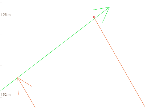
Placing a start point at the beginning of a track.
3.g Make Route
To generate the route, open the Make Route-function and select the tracks fitted to the headland as Crop Tracks, the headland as Headland Tracks, and your start and end points if you created them.
Min Track Length sets the level for the shortest length a line segment can be and still be included as a row. Max Midrow Angle sets the maximum degrees the robot can turn at a point in the middle of a row. These two rarely need adjustment.
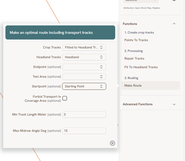
Configuring the Make Route function.
The result should look something like this:
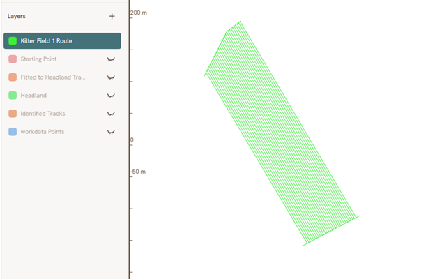
The generated route.
If there is a problem with any of the rows — for example, intersecting tracks — a new layer called Routing Validation Error appears, and the route cannot be created until this is resolved.
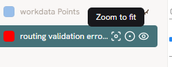
A routing validation error layer.
Click Zoom to Fit on the error layer to locate the problem, fix it, delete the error layer, and try the Make Route function again. Repeat if further errors appear.
If it is difficult to see what the issue is, you can right-click the layer and select attributes. This will open a table showing the validation reason and what row(s) it concerns.
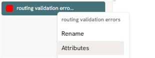
Selecting Attributes from the right-click menu.
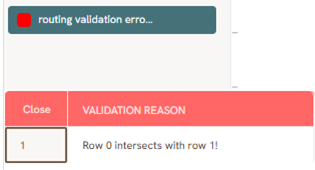
The attribute table, showing the validation reason and the affected row(s).
4. Publishing the Route
To upload the route to the AX-1 robot, click the field name in the top-left corner to open the dropdown menu, then choose Publish Route. This will also save your workspace.
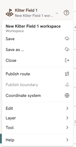
Opening the Publish Route option.
Select the route you want to publish and click Next.
If you publish a route with the same name as a previously existing route in the same field, it will create a new version of it. A route with a new name will become a new route.
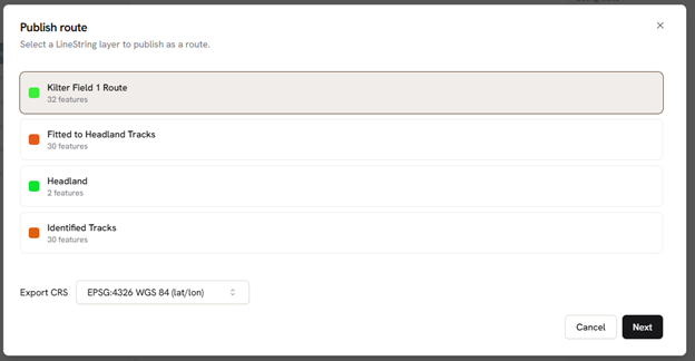
Selecting the route to publish.
Review the route preview and check for any remaining issues, listed on the right-hand side.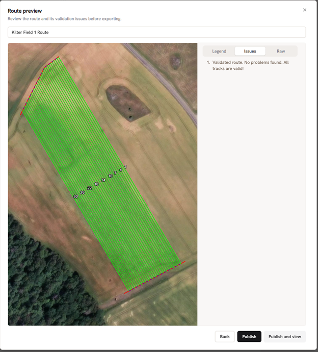
Reviewing the route preview and issues.
Here you have two options. Choosing Publish keeps you in the workspace after publishing. Choosing Publish and View takes you out of the workspace to view the route under Routes, inside the field. Either way, the route will be uploaded to the robot.
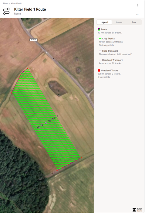
The published route.
The upload should not take long. If it does not upload within a couple minutes, try to refresh the app or restart the robot.
When a route is published, you can see the version of the route in the top right corner.
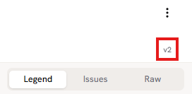
The route version shown in the top-right corner.
If you select this you can restore it to previous versions of the route by clicking Restore on the correct version.
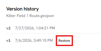 Restoring a previous version of the route.
The restored version will then appear as a new version, here v3.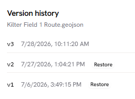
It is not uncommon that you will find a need for some adjustments after a test run of a new route. This way you can test adjustments through the various tools and functions, but always come back to previous published versions.
5. Other Useful Tools
Beyond the core route-building steps, a few general layer-editing tools are useful throughout Kilter Farm.
5.a Flatten
Flatten merges two or more layers into one. Select the layers you want to merge in the layer panel — click the first, then hold Ctrl and click the others. Selected layers are highlighted with a light blue tint. Right-click one of the selected layers and choose Flatten from the menu.
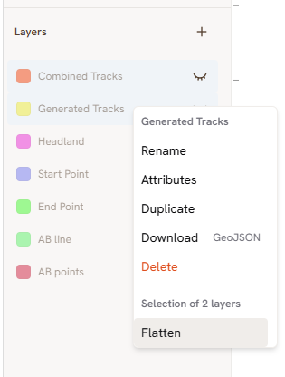
Selecting two layers and choosing Flatten.
5.b Paste with Offset
Paste With Offset creates a copy of one or more lines at a set distance from the original. Select the lines you want to copy, right-click and choose Copy (or press Ctrl+C), then right-click again and choose Paste With Offset, followed by Left, Right, or Both. Then you will choose the distance for the offset. Note that this works best with straight lines, and that curved and more complex lines will create less predictable results.
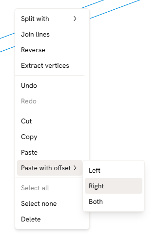
Choosing Paste with Offset after copying a line.
The offset direction is relative to the direction of the line. Toggle Arrows in the layer appearance menu to check which way a line points.
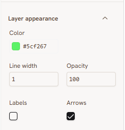
Enabling Arrows in the layer appearance menu.
5.c Extract Vertices
Extract Vertices creates a new point layer containing every vertex of the selected lines.
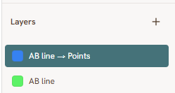
The new point layer created by Extract Vertices.
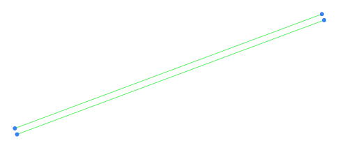
Vertices extracted from two lines.
5.d Split with
Split With splits lines using a line. Create a new LineString layer and draw one or more lines across the lines you want to split, where you want the cuts to be. Select the layer containing the lines you want to split and select the relevant lines. Right-click, choose Split With, and select the LineString layer you just drew to split the lines. This creates a new layer containing the split lines.
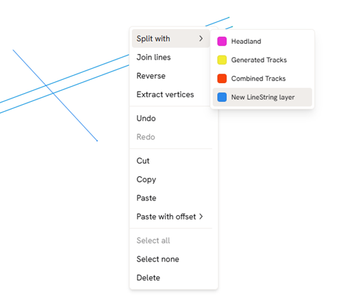 Choosing Split With and selecting the cutting layer.
5.e Reverse
Reverse flips the direction of one or more lines. Select the lines, right-click, and choose Reverse.
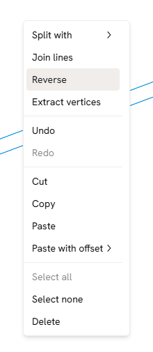 Choosing Reverse from the right-click menu.
5.f Manually Choose CRS
There are usually two reasons for wanting to manually set the CRS:
-
The most common one is a missing .prj file from the shapefile. The best solution here is usually to reexport the data with the .prj file included as the correct CRS will be autodetected. More info on shapefiles and file types can be found in section 1.b File Types.
-
There is some unexplained offset in several routes from the same data source. It can be useful to test different CRSs to check if that is the problem.
5.f.i .prj is Missing
If you are not able to reexport the file with the .prj file included, contact your GPS/GNSS provider and if they cannot help you with reexport, ask them for the CRS they use, so that you can input it manually.
5.f.ii Unexplained Offset
If you want to test different CRSs, simply ensure that the .prj file is removed from your shapefile, and you will get the option to choose as seen in the images below.
The first place you can encounter this is when uploading a boundary to create a field. Pick the correct CRS in the dropdown menu. If you are uncertain of which CRS is the correct one and your farm is in Europe, the top one (EPSG:4326 WGS 84) is usually a safe bet.
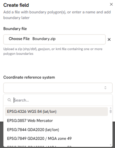
Choosing the CRS when uploading a field boundary.
For the workspace, the same applies, but here you can choose the CRS for both the workspace and the files. Choose the correct CRS for your area as the workspace CRS. Try to manually choose what is thought to be the CRS of your file and use the same one for the workspace. If this does not work, try other likely combinations or contact Kilter Support at support@kiltersystems.com.
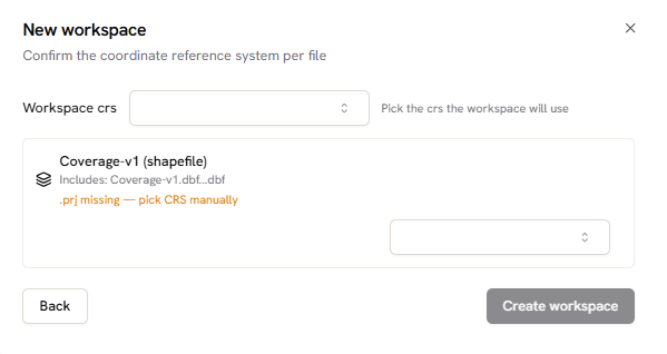
Choosing the CRS for the uploaded files.
6. Advanced Functions
The functions below are not required for every route, but are useful for more complex fields or for adjusting an existing set of tracks.
6.a Generate Tracks
Generate Tracks creates evenly spaced parallel tracks across a field from a single AB-line and headland. See Section 3.d.ii Generate Tracks for a full walkthrough of the function's settings.
6.b Track Processing
6.b.i Combine Tracks
Combine Tracks reduces the number of tracks by grouping adjacent lines into a single driving track, based on the Tracks Per Group value. Setting this to 3, for example, groups every three lines into one — similar to keeping only every third line. You can also set an overlap between groups, which is useful if you want some tracks to be covered twice, for example when spraying.
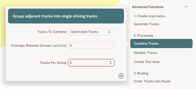
Configuring the Combine Tracks function.
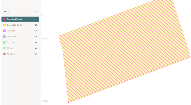
Combined Tracks (red) alongside the original Generated Tracks (yellow).
6.b.ii Multiply Tracks
Multiply Tracks creates additional offset tracks from each input track, at the offsets you specify. Entering 1.8, -1.8, for example, creates one track 1.8 m to one side and one 1.8 m to the other side of each original track in a new layer.
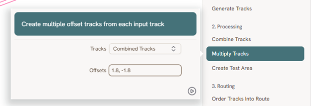
Configuring the Multiply Tracks function.
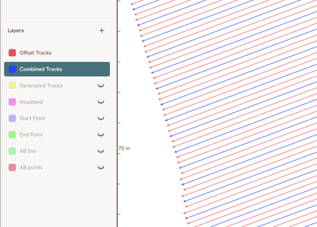
The resulting offset tracks.
The original and offset tracks can be merged into a single layer. Select both layers in the layer panel — click the first, then Ctrl+click the second — and choose Flatten from the right-click menu (not Combine).
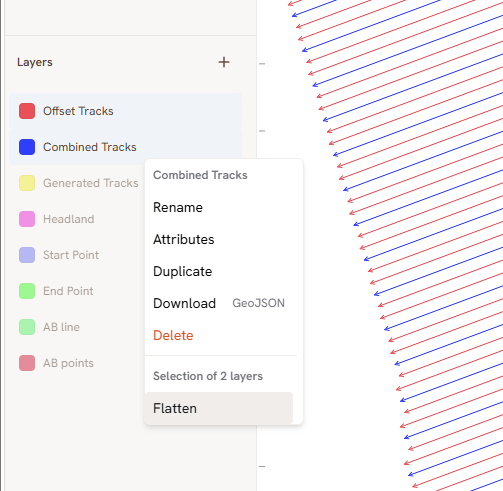
Selecting two layers and using Flatten.
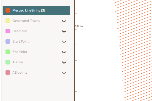
The merged layer after flattening.
6.b.iii Create Test Area
This function is outdated. It will either be removed or updated.
6.c Order Tracks into Route
Order Tracks Into Route is another way to build a route, using sorting lines to set the order in which tracks are driven. This is useful, for example, if you want to drive every other row in one direction and pick up the remaining rows on the way back.
Create a new LineString layer for the sorting line. The order in which this line crosses the tracks determines the order they are driven in. Each new line you draw continues the sequence from the previous one, so you can either draw a separate line for each track in the order you want, or a single zigzag line, as shown below.
Warning Sorting lines override the headland and drive in a straight line from the end of one row to the next line selected by the sorting line. This will often overlap with the headland, but sometimes it creates transport lines across other rows. Check this before publishing.
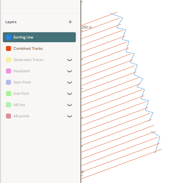
A zigzag sorting line crossing the tracks.
Once you have created your sorting lines, run the Order Tracks Into Route-function.
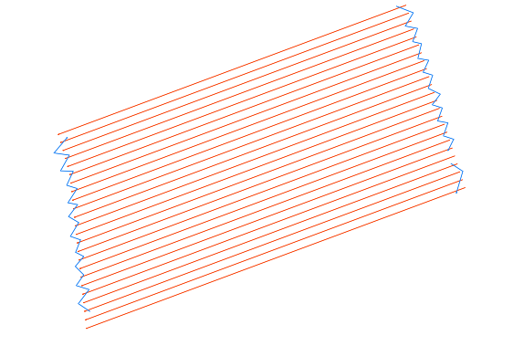
The sorting line and tracks before ordering.
You can also control which direction the route drives in by adding a starting point — see 3.f Start and end points. For this case, only a starting point is used: it decides the direction of the first line, which in turn decides the direction of every line after it. Placing the starting point on the other side of the first line will mirror the whole route.
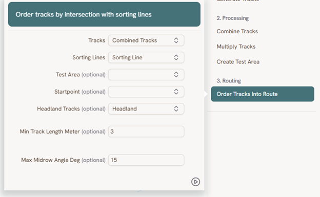
Configuring the Order Tracks Into Route function.
Turn on Labels in the layer's appearance settings to inspect the resulting order.
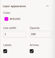
Enabling labels in the layer appearance settings.
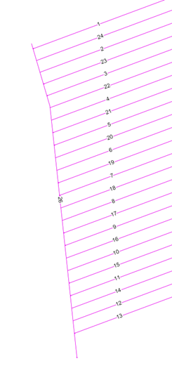 The resulting track order, following the zigzag sorting line.